GOST 2.311-68
Group T52
INTERSTATE STANDARD
Unified system for design documentation
Unified system for design documentation. image of screw
ISS 01.100.20
Introduction date 1971-01-01
INFORMATION DATA
1. DEVELOPED AND INTRODUCED by the Committee of Standards, Measures and Measuring Instruments under the Council of Ministers of the USSR
2. APPROVED AND INTRODUCED BY Decree of the Committee of Standards, Measures and Measuring Instruments under the Council of Ministers of the USSR dated May 28, 1968 N 755
3. The standard corresponds to ST SEV 284-76
4. REPLACE GOST 3459-59
5. EDITION (August 2007) with Amendment No. 1 approved in April 1987 (IUS 7-87)
1. This standard establishes the rules for the image and application of the thread designation in the drawings of all industries and construction.
The standard complies with ST SEV 284-76.
2. The carving is depicted:
a) on the rod - with solid main lines along the outer diameter of the thread and solid thin lines - along inner diameter.
On images obtained by projecting onto a plane parallel to the axis of the rod, a solid thin line along the inner diameter of the thread is drawn for the entire length of the thread without run-off, and on views obtained by projecting onto a plane perpendicular to the axis of the rod, along
to the inner diameter of the thread, an arc is drawn approximately equal to a circle, open anywhere (Fig. 1, 2);
b) in the hole - with solid main lines along the inner diameter of the thread and solid thin lines - along the outer diameter.
On cuts parallel to the axis of the hole, a solid thin line along the outer diameter of the thread is drawn for the entire length of the thread without runoff, and on images obtained by projecting onto a plane perpendicular to the axis of the hole, an arc is drawn along the outer diameter of the thread,
approximately equal to a circle, open anywhere (Fig. 3, 4).
A solid thin line when depicting a thread is applied at a distance of at least 0.8 mm from the main line and not more than the thread pitch.
3. The thread, shown as invisible, is depicted by dashed lines of the same thickness along the outer and inner diameters (Fig. 5).
4. The line defining the thread boundary is applied on the rod and in the threaded hole at the end of the full thread profile (before the start of the run). The thread boundary is drawn to the line of the outer diameter of the thread and is depicted as a solid main or dashed line if the thread is shown as invisible (Fig. 6-8).

5. Hatching in sections and sections is carried out to the line of the outer diameter of the thread on the rods
and to the line of the inner diameter in the hole, i.e. in both cases to a solid main line
(see fig. 3, 4, 7, 8).
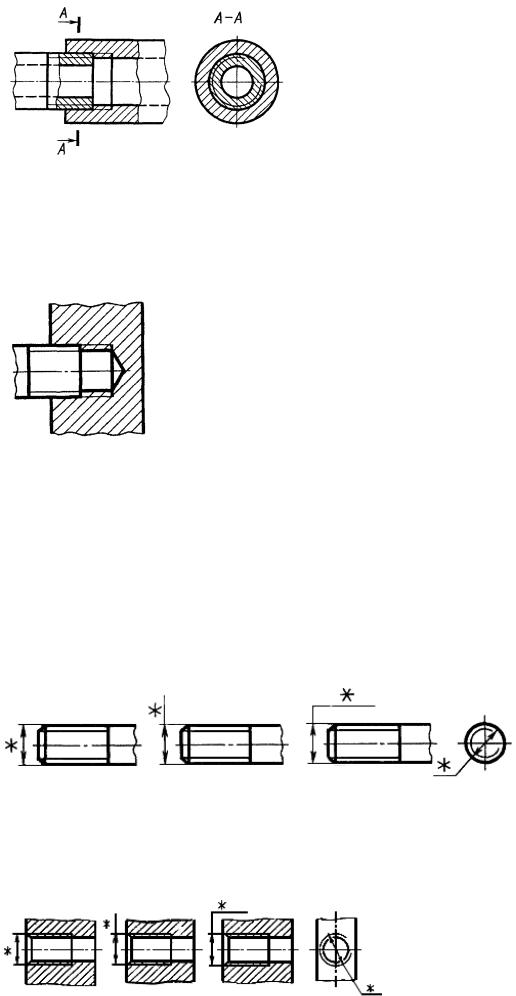
6. The size of the length of the thread with a full profile (without run-off) on the rod and in the hole is indicated, as shown in Fig. 9a and 10a.
The size of the thread length (with a run) is indicated, as shown in Fig. 9b and 10b.
If it is necessary to indicate the amount of run-off on the rod, the dimensions are applied, as shown in Fig. 9c.
The thread run is depicted as a solid thin straight line, as shown in Fig. 9b, c and 10b.

The undercut of the thread, made to the stop, is depicted as shown in Fig. 11a and c.
It is allowed to depict a thread undercut, as shown in Fig. 11b and d.
7. The main plane of the tapered thread on the rod, if necessary, is indicated by a thin solid line, as shown in Fig.12.
8. In the drawings, according to which the thread is not made, the end of a blind threaded hole is allowed to be depicted as shown in Figures 13 and 14, even if there is a difference between the depth of the threaded hole and the length of the thread.
9. Chamfers on a threaded rod and in a threaded hole that do not have a special design purpose, in projection onto a plane perpendicular to the axis of the rod or hole, are not depicted (Fig. 15-17). A solid thin line of the image of the thread on the rod must intersect the chamfer boundary line (see drawing 15).

10. A thread with a non-standard profile is shown in one of the ways shown in Fig. 18, with all the necessary dimensions and maximum deviations. In addition to the dimensions and maximum deviations of the thread, the drawing indicates additional data on the number of entries, on the left direction of the thread, etc. with the addition of the word "Carving".
11. On sections of a threaded connection in the image on a plane parallel to its axis, only the part of the thread that is not covered by the thread of the rod is shown in the hole (Fig. 19, 20).
12. The designations of the threads indicate, according to the relevant standards, the dimensions and maximum deviations of the threads and refer them for all threads, except for conical and cylindrical pipe threads, to the outer diameter, as shown in Fig. 21, 22.

The designations of conical threads and cylindrical pipe threads are applied as shown in drawing 23.
Note. The "*" sign marks the places where the thread designation is applied.
13. Special threads with a standard profile are abbreviated as Sp and symbol threads.
(Changed edition, Rev. N 1).
The electronic text of the document was prepared by CJSC "Kodeks" and verified by: official publication
Unified system of design documentation: Sat. GOSTs. - M.: Standartinform, 2007
GOST 2.311-68
INTERSTATE STANDARD
UNIFIED SYSTEM OF DESIGN DOCUMENTATION
THREAD IMAGE
Official edition
Standartinform
ME GOVERNMENT STANDARD
Unified system of design documentation
THREAD IMAGE
Unified system for design documentation.
ISS 01.100.20
Introduction date 01.01.71
1. This standard establishes the rules for the image and application of the thread designation in the drawings of all industries and construction.
The standard complies with ST SEV 284-76.
2. The carving is depicted:
a) on the rod - with solid main lines along the outer diameter of the thread and solid thin lines - along the inner diameter.
On images obtained by projecting onto a plane parallel to the axis of the rod, a solid thin line along the inner diameter of the thread is drawn for the entire length of the thread without run-off, and on views obtained by projecting onto a plane perpendicular to the axis of the rod, an arc is drawn along the inner diameter of the thread, approximately equal to * 1 2 3/4 circles, open anywhere (Fig. 1.2);


b) in the hole - with solid main lines along the inner diameter of the thread and solid thin lines - along the outer diameter.
On cuts parallel to the axis of the hole, a solid thin line along the outer diameter of the thread is drawn for the entire length of the thread without run-off, and on images obtained by projecting onto a plane perpendicular to the axis of the hole, an arc is drawn along the outer diameter of the thread, approximately equal to 3/4 of the circle, open anywhere (Fig. 3.4).


Official Edition ★
Reprint prohibited
© Standartinform, 2007
A solid thin line when depicting a thread is applied at a distance of at least 0.8 mm from the main line and not more than the thread pitch.
3. The thread, shown as invisible, is depicted by dashed lines of the same thickness along the outer and inner diameters (Fig. 5).
4. The line defining the thread boundary is applied on the rod and in the threaded hole at the end of the full thread profile (before the start
escape). The thread boundary is drawn to the line of the outer diameter of the thread and is depicted as a solid main or dashed line if the thread is shown as invisible (Fig. 6-8).
A-A

A-A

5. Hatching in sections and sections is carried out to the line of the outer diameter of the thread on the rods and to the line of the inner diameter in the hole, i.e. in both cases to a solid main line (see Fig. 3, 4, 7, 8).
6. The length of the thread with a full profile (without run-off) on the rod and in the hole is indicated as shown in Fig. 9a and 10a.
The size of the thread length (with a run) is indicated as shown in Fig. 96 and 10b.
If it is necessary to indicate the amount of run-off on the rod, the dimensions are applied, as shown in Fig. 9th century
The thread run is depicted as a solid thin straight line, as shown in Fig. 9b, c and 106.


The undercut of the thread, made to the stop, is depicted as shown in Fig. Pai in. It is allowed to depict a thread undercut, as shown in Fig. 1 \b and d.


7. The main plane of the tapered thread on the rod, if necessary, is indicated by a thin solid line, as shown in Fig. 12.
8. In the drawings, according to which the thread is not performed, the end of a blind threaded hole is allowed to be depicted, as shown in Fig. 13 and 14 even if there is a difference between the depth of the threaded hole and the thread length.


9. Chamfers on a threaded rod and in a threaded hole that do not have a special design purpose, in projection onto a plane perpendicular to the axis of the rod or hole, do not depict (Fig. 15-17). A solid thin line of the image of the thread on the rod must cross the line of the chamfer boundary (see Fig. 15).


10. A thread with a non-standard profile is shown in one of the ways shown in Fig. 18, with all the necessary dimensions and limit deviations. In addition to the dimensions and maximum deviations of the thread, the drawing indicates additional data on the number of entries, on the left direction of the thread, etc. with the addition of the word "Carving".

11. On sections of a threaded connection in the image on a plane parallel to its axis, only the part of the thread that is not closed by the thread of the rod is shown in the hole (Fig. 19, 20).


12. The designations of the threads indicate, according to the relevant standards, the dimensions and limit deviations of the threads and refer them for all threads, except for conical and cylindrical pipe threads, to the outer diameter, as shown in Fig. 21, 22.


The designations of conical threads and cylindrical pipe threads are applied as shown in Fig. 23.
Note. The "*" sign marks the places where the thread designation is applied.
13. A special thread with a standard profile is abbreviated as C and a thread symbol.
(Revised edition, Rev. No. 1).
1. DEVELOPED AND INTRODUCED by the Committee of Standards, Measures and Measuring Instruments under the Council of Ministers of the USSR
2. APPROVED AND INTRODUCED BY Decree of the Committee of Standards, Measures and Measuring Instruments under the Council of Ministers of the USSR dated May 28, 1968 No. 755
3. The standard complies with ST SEV 284-76
4. REPLACE GOST 3459-59
5. EDITION (August 2007) with Amendment No. 1 approved in April 1987 (IUS 7-87)


The construction of a helical surface on the drawing is a long and difficult process, therefore, in the drawings of products, the thread is depicted conditionally, in accordance with GOST 2.311–68. The helix is replaced by two lines - a solid main line and a solid thin line.
Threads are subdivided according to their location on the surface of the part into external and internal.
Conditional image of a thread on a rod.
Fig.7
The external thread on the rod (Fig. 7) is depicted by solid main lines along the outer diameter and solid thin lines along the inner diameter, and on images obtained by projecting onto a plane perpendicular to the axis of the rod, a thin line is drawn on 3/4 of the circle, and this line can be open anywhere (it is not allowed to start a solid thin line and end it on the center line). The distance between a thin line and a solid main line should not be less than 0.8 mm and more than the thread pitch, and the chamfer is not shown in this view. The thread boundary is applied at the end of the complete thread profile (before the start of the run) with a solid main line, if it is visible. The thread run, if necessary, is depicted as a solid thin line.
Fig.8
For technological reasons, thread undercutting can be carried out on a part of a part (rod). In total, the thread undercut and the run-out are the thread undercut (GOST 10548–80). The size of the thread length is indicated, as a rule, without a run.
Symbolic image of a thread in a hole
Fig.9
Internal thread – is depicted as a solid main line along the inner diameter and a solid thin line along the outer one. If, when depicting a blind hole, the end of the thread is located close to its bottom, then it is allowed to depict the thread to the end of the hole. Threads with a non-standard profile should be depicted.
Conditional image of the thread assembly.
Fig.10
On sections of a threaded connection in the image on a plane parallel to its axis in the hole, only the part of the thread that is not covered by the thread of the rod is shown.
Hatching in cuts and sections is carried out to a solid main line, i.e. to the outer diameter of the outer thread and the inner diameter of the inner thread.
Table 4. Symbolic image of threads
To designate threads, standards for individual types of threads are used. For all threads, except for conical and cylindrical pipe threads, the designations refer to the outer diameter and are placed above the dimension line, on its continuation, or on the shelf of the leader line. The designations of conical threads and cylindrical pipe threads are applied only on the shelf of the leader line.
The thread in the drawing is conventionally designated in accordance with the standards for the image, diameters, steps, etc.
Metric thread is designated in accordance with GOST 9150–81.
Metric thread subdivided into threads with a large pitch, denoted by the letter M indicating the nominal diameter of the cylindrical surface on which the thread is made, for example M12, and a fine pitch thread, indicated by indicating the nominal diameter, thread pitch and tolerance field, for example M24´2-6g or M12´1-6H.
When designating a left-hand thread, LH is placed after the symbol.
Multi-start threads are designated, for example, three-start, М24´З(P1)LH, where M- thread type, 24 - nominal diameter, 3 - thread stroke, P 1 - thread pitch. The given designations of left-hand and multi-start threads can be applied to all metric threads.
Metric taper thread designated in accordance with GOST 25229–82. The thread designation includes the letters MK. Connections of an internal cylindrical thread with an external conical thread are used. The dimensions of the profile elements of conical and cylindrical threads are taken in accordance with GOST 9150–81. This type of connection must ensure that the taper thread is screwed in to a depth of at least 0.8 l(where l- thread length without run-out). The designation of an internal cylindrical thread consists of a nominal diameter, a pitch and a standard number (for example: M20´1.5 GOST 25229–82).
Fig.11
The connection of an internal cylindrical thread with an external conical thread (Fig. 11) is indicated by the M / MK shot, nominal diameter, pitch and standard number: M / MK 20´1.5LH GOST 25229–82. In the absence of special requirements for the density of connections of this kind or when seals are used to achieve the tightness of such connections, the standard number in the designation of the connections is omitted, for example: M / MK 20´1.5 LH.
The tolerance field of the average diameter of the internal cylindrical thread must correspond to 6N according to GOST 16093–81, and the maximum deviation of the internal diameter and the cut of the hollows of the internal cylindrical thread is taken within the limits: upper limit deviation (+0.12) ... (+0.15), and the lower limit deviation is 0.
Pipe cylindrical thread. The thread symbol consists of the letter G, designation of the thread size, accuracy class of the average diameter ( BUT or AT). For left-hand threads, the symbol LH is used. For example, G1 1 / 2 LH-B-40 make-up length, if required.
The connection of an internal cylindrical pipe thread of accuracy class A with an external pipe conical thread according to GOST 6211–81 is designated as follows: for example, G / R p -1 1 / 2 -A.
When designating landings, the numerator indicates the accuracy class of the internal thread, and the denominator indicates the external thread. For example: G 1 1 / 2 -A / B.
Pipe taper thread. The thread designation includes the letters: R– for tapered external thread, R c - for tapered internal thread, R p - for a cylindrical internal thread and thread size designation. For left-hand threads, the letters LH are added. The conditional size of the thread, as well as its diameters measured in the main plane, correspond to the parameters of a cylindrical pipe thread having the same conditional size. Therefore, parts with pipe conical threads are quite often used in connections with parts with cylindrical pipe threads, which ensures a sufficiently high tightness of the connections. Threaded connections are designated as a fraction, in the numerator of which the letter designation of the internal thread is indicated, and in the denominator - the external one. Designation example:
Internal pipe cylindrical thread of accuracy class BUT according to GOST 6357–81.
Trapezoidal carving. Trapezoidal thread symbol consists of letters Tr, nominal diameter, stroke R n and step R. For example: Tr20´4LH–8H, where LH is the designation of the left thread, 8H is the main thread deviation.
If necessary, the main thread deviation is followed by the make-up length. L(in mm). For example: Tg40´6–8g–85; 85 - make-up length.
The carving is persistent. The thread designation consists of a letter S, nominal diameter, pitch and basic deviation S80´10–8Н.
For a left-hand thread, the letters LH are indicated after the thread symbol.
For a multi-start thread, an additional stroke value is entered together with the letter R and step value. So, a two-start thread with a pitch of 10 mm is designated S80´2 (P10).
Rectangular thread not standardized. When depicting a rectangular thread, it is recommended to draw a local section on which the necessary dimensions are put down.
Special threads. If the thread has a standard profile, but differs from the corresponding standard thread in diameter or pitch, then the thread is called special. In this case, the inscription is added to the thread designation sp, and the thread designation indicates the dimensions of the outer diameter and thread pitch, for example: Sp.M19´1D. A thread with a non-standard profile is depicted as it is presented in clause 9 of Table 1, with the dimensions necessary for the manufacture of the thread.
Technological thread elements
Fig.12
Metric, single-thread, trapezoidal, cylindrical pipe, conical pipe, inch conical threads with a profile angle of 60° have technological elements associated with the exit of the thread, which include: runaway, undercut, groove and chamfer.
Chamfers are threaded. GOST 10549–80
Chamfers on rods and in threaded holes (except for metric threads) have the shape of a truncated cone with an angle at the apex of 90 ° and a height Z. Chamfers on metric external threads have a taper angle of 90° and a specified diameter of the smaller taper base. Chamfers on metric female threads have a cone angle of 120° and a specified diameter of the larger base of the truncated cone. Chamfers are depicted only on a projection parallel to the axis of the thread, or in section with a plane passing through the axis of the thread. On the projection onto a plane perpendicular to the axis of the thread, the chamfer is not shown.
The shape and dimensions of chamfers for external metric threads, fasteners are established by GOST 12414–66 (ST SEV 215–82). The determining dimension is the outer diameter of the thread d. The shape and dimensions of chamfers for internal metric threads are established by GOST 10549–80. The determining dimension is the outer diameter of the thread D.
The shape and dimensions of chamfers for trapezoidal threads are established by GOST 10549–80. The determining dimension is the thread pitch R.
The shape and dimensions of the chamfers for pipe conical threads and conical inch threads are established by GOST 10549–80. The determining parameter is the number of thread pitches over a length of 25.4 mm . The shape and dimensions of chamfers for cylindrical pipe threads are established by GOST 10549–80. The determining parameter is the number of thread pitches over a length of 25.4 mm .
Threaded grooves. GOST 10549–80
Fig.13
A groove (Fig. 13) is made at the end of the thread to exit the tool and obtain a full profile thread along the entire length of the rod or hole. In the drawings of the part, the groove is depicted in a simplified way and the drawing is supplemented with an external element on an enlarged scale .
The shape and dimensions of the grooves of the external thread (when threading is threaded) are established by GOST 10549–80 (ST SEV 214–75). The determining dimension is the thread pitch R.
The shape and dimensions of the grooves for internal metric threads are established by GOST 10549–80. The determining dimension is the thread pitch R.
The shape and dimensions of the grooves for trapezoidal threads are established by GOST 10549–80. The determining dimension is the thread pitch R.
The shape and dimensions of the grooves for pipe conical threads and conical inch threads are established by GOST 10549–80. The determining parameter is the number of thread pitches over a length of 25.4 mm .
The shape and dimensions of the grooves for cylindrical pipe threads are established by GOST 10549–80. The determining parameter is the number of thread pitches over a length of 25.4 mm .
GOST 2.311-68
Group T52
INTERSTATE STANDARD
Unified system of design documentation
THREAD IMAGE
Unified system for design documentation. image of screw
ISS 01.100.20
Introduction date 1971-01-01
INFORMATION DATA
1. DEVELOPED AND INTRODUCED by the Committee of Standards, Measures and Measuring Instruments under the Council of Ministers of the USSR
2. APPROVED AND PUT INTO EFFECT by the Decree of the Committee of Standards, Measures and Measuring Instruments under the Council of Ministers of the USSR of May 28, 1968 N 755
3. The standard complies with ST SEV 284-76
4. REPLACE GOST 3459-59
5. EDITION (August 2007) with Amendment No. 1 approved in April 1987 (IUS 7-87)
1. This standard establishes the rules for the image and application of the thread designation in the drawings of all industries and construction.
The standard complies with ST SEV 284-76.
2. The carving is depicted:
a) on the rod - with solid main lines along the outer diameter of the thread and solid thin lines - along the inner diameter.
On images obtained by projecting onto a plane parallel to the axis of the rod, a solid thin line along the inner diameter of the thread is drawn for the entire length of the thread without run-off, and on views obtained by projecting onto a plane perpendicular to the axis of the rod, an arc is drawn along the inner diameter of the thread, approximately equal to circle, open anywhere (Fig. 1, 2);
Damn.1
Damn.2
b) in the hole - with solid main lines along the inner diameter of the thread and solid thin lines - along the outer diameter.
On cuts parallel to the axis of the hole, a solid thin line along the outer diameter of the thread is drawn for the entire length of the thread without run-off, and on images obtained by projecting onto a plane perpendicular to the axis of the hole, an arc is drawn along the outer diameter of the thread, approximately equal to a circle open in any place (Fig. 3, 4).
Damn.3
Damn.4
A solid thin line when depicting a thread is applied at a distance of at least 0.8 mm from the main line and not more than the thread pitch.
3. The thread, shown as invisible, is depicted by dashed lines of the same thickness along the outer and inner diameters (Fig. 5).
Damn.5
4. The line defining the thread boundary is applied on the rod and in the threaded hole at the end of the full thread profile (before the start of the run). The thread boundary is drawn to the line of the outer diameter of the thread and is depicted as a solid main or dashed line if the thread is shown as invisible (Fig. 6-8).
Damn.7
Damn.8
5. Hatching in sections and sections is carried out to the line of the outer diameter of the thread on the rods and to the line of the inner diameter in the hole, i.e. in both cases to a solid main line (see Fig. 3, 4, 7, 8).
6. The size of the length of the thread with a full profile (without run-off) on the rod and in the hole is indicated as shown in Fig. 9 a and 10 a.
The size of the thread length (with a run) is indicated as shown in Fig. 9 b and 10 b.
If it is necessary to indicate the amount of run-off on the rod, the dimensions are applied as shown in Fig. 9 in.
The thread run is depicted as a solid thin straight line, as shown in Fig. 9 b, in and 10 b.
Damn.9
Damn.10
The undercut of the thread, made to the stop, is depicted as shown in Fig. 11 a and in.
It is allowed to depict a thread undercut, as shown in Fig. 11 b and G.
7. The main plane of the tapered thread on the rod, if necessary, is indicated by a thin solid line, as shown in Fig.12.
Devil 12
8. In the drawings, according to which the thread is not made, the end of a blind threaded hole is allowed to be depicted as shown in Figures 13 and 14, even if there is a difference between the depth of the threaded hole and the length of the thread.
Damn.13
Devil 14
9. Chamfers on a threaded rod and in a threaded hole that do not have a special design purpose, in projection onto a plane perpendicular to the axis of the rod or hole, are not depicted (Fig. 15-17). A solid thin line of the image of the thread on the rod must intersect the chamfer boundary line (see drawing 15).
Damn.15
Devil 16
Damn.17
10. A thread with a non-standard profile is shown in one of the ways shown in Fig. 18, with all the necessary dimensions and maximum deviations. In addition to the dimensions and maximum deviations of the thread, the drawing indicates additional data on the number of entries, on the left direction of the thread, etc. with the addition of the word "Carving".
11. On sections of a threaded connection in the image on a plane parallel to its axis, only the part of the thread that is not covered by the thread of the rod is shown in the hole (Fig. 19, 20).
Damn.19
Damn.20
12. The designations of the threads indicate, according to the relevant standards, the dimensions and maximum deviations of the threads and refer them for all threads, except for conical and cylindrical pipe threads, to the outer diameter, as shown in Fig. 21, 22.
Damn.21
Damn.22
The designations of conical threads and cylindrical pipe threads are applied as shown in drawing 23.
Damn.23
Note. The "*" sign marks the places where the thread designation is applied.
13. A special thread with a standard profile is abbreviated as Sp and a thread symbol.
(Changed edition, Rev. N 1).
Electronic text of the document
prepared by Kodeks JSC and verified against:
official publication
Unified system of design documentation:
Sat. GOSTs. - M.: Standartinform, 2007
GOST 2.311-68
INTERSTATE STANDARD
UNIFIED SYSTEM OF DESIGN DOCUMENTATION
THREAD IMAGE
IPK STANDARDS PUBLISHING HOUSE
Moscow
INTERSTATE STANDARD
|
Unified system of design documentation IMAGETHREADS Unified system for design documentation. |
GOST |
Introduction date 01.01.71
1. This standard establishes the rules for the image and application of the thread designation in the drawings of all industries and construction.
The standard complies with ST SEV 284-76.
2. The carving is depicted:
a) on the rod - with solid main lines along the outer diameter of the thread and solid thin lines - along the inner diameter.
On images obtained by projecting onto a plane parallel to the axis of the rod, a solid thin line along the inner diameter of the thread is drawn for the entire length of the thread without run-off, and on views obtained by projecting onto a plane perpendicular to the axis of the rod, an arc is drawn along the inner diameter of the thread, approximately equal to 3/4 of a circle, open anywhere (hell,);
Crap. one

Crap. 2
b) in the hole - with solid main lines along the inner diameter of the thread and solid thin lines - along the outer diameter.
On cuts parallel to the axis of the hole, a solid thin line along the outer diameter of the thread is drawn for the entire length of the thread without run-off, and on images obtained by projecting onto a plane perpendicular to the axis of the hole, an arc approximately equal to 3/4 of the circle is drawn along the outer diameter of the thread, open anywhere (hell, ).

Crap. 3

Crap. four
A solid thin line when depicting a thread is applied at a distance of at least 0.8 mm from the main line and not more than the thread pitch.
3. The thread, shown as invisible, is depicted by dashed lines of the same thickness along the outer and inner diameters (Fig.).

Crap. 5
4. The line defining the thread boundary is applied on the rod and in the threaded hole at the end of the full thread profile (before the start of the run). The thread boundary is drawn to the line of the outer diameter of the thread and is depicted as a solid main or dashed line if the thread is shown as invisible (Fig. -).

Crap. 6

Crap. 7

Crap. eight
5. Hatching in sections and sections is carried out to the line of the outer diameter of the thread on the rods and to the line of the inner diameter in the hole, i.e. in both cases to a solid main line (see Fig. , , , ).
6. The length of the thread with a full profile (without run-off) on the rod and in the hole is indicated as shown in Fig. a and hell. a.
The size of the thread length (with a run) is indicated as shown in Fig. b and hell. b.
If it is necessary to indicate the amount of run-off on the rod, the dimensions are applied, as shown in Fig. in.
The thread run is depicted as a solid thin straight line, as shown in Fig. b, in and hell. b.

Crap. 9

Crap. ten
The undercut of the thread, made to the stop, is depicted as shown in Fig. a and in.
It is allowed to depict a thread undercut, as shown in Fig. b and G.

Crap. eleven
(Revised edition, Rev. No. 1).
7. The main plane of the tapered thread on the rod, if necessary, is indicated by a thin solid line, as shown in Fig. .

Crap. 12
8. In the drawings, according to which the thread is not performed, the end of a blind threaded hole is allowed to be depicted, as shown in Fig. and , even if there is a difference between the depth of the tap hole and the length of the thread.

Crap. 13

Crap. fourteen
9. Chamfers on a threaded rod and in a threaded hole that do not have a special design purpose, in projection onto a plane perpendicular to the axis of the rod or hole, do not depict (Fig. -). A solid thin line of the image of the thread on the rod must intersect the chamfer boundary line (see Fig.).

Crap. fifteen

Crap. 16

Crap. 17
10. A thread with a non-standard profile is shown in one of the ways shown in Fig. , with all the necessary dimensions and limit deviations. In addition to the dimensions and maximum deviations of the thread, the drawing indicates additional data on the number of entries, on the left direction of the thread, etc. with the addition of the word "Carving".

Crap. eighteen
11. On sections of a threaded connection in the image on a plane parallel to its axis, only the part of the thread that is not covered by the thread of the rod is shown in the hole (Fig.


How to disable ads on Android: remove pop-up ads
The Russian received a term and a million fine for "piracy Negative consequences of the law
Identification of key factors
The criteria for classifying organizations and individual entrepreneurs as small and medium-sized businesses have changed
See what "Royalty" is in other dictionaries Pitfalls of legislation