"Electricity in squares" or how I made an electronic designer from improvised materials
- DIY or DIY,
- Games and game consoles
The idea of creating an electronic construction set has been on my mind for a long time. As a child, I had an EKON-1 constructor and I wanted to create something similar, but at a modern level. The Connoisseur rules the ball on the market, there are also examples of modular constructors abroad, but the price and exchange rate are not pleasing to the eye.
On the other hand, there were interesting developments in the USSR (one of them still lives in Germany and is being produced).
I also wanted something “warm” in materials, such as wood. In 2014, within the framework of the PROSTOROBOT project, the idea of electronic cubes was born, which in 2015 even received a prize from AIDT for the idea at one of the qualifying stages of the Startup Tour.
Also at this time, I came up with the logic board game "Chain", which allowed you to play " electrical circuits". The game can be freely downloaded and printed from the link.
Time passed. The cubes had to be put aside, since the price of magnets of the required power made them quite expensive. The game "Chain" waited for its turn to be finalized.
In 2016, I decided to return to the project and "got" the cubes. The first idea was to use the same cubes, but make fasteners like spring contacts and glue a cardboard box with cells, on the walls of which the contacts would be located:

The design turned out to be cumbersome, and due to the low rigidity of the walls, the cubes did not provide the desired quality of contact.
Engineering thought moved on. A small digression on the choice of material. Can you reasonably say why I did not use 3D printing or laser cutting? The answer is simple - I don’t have a 3D printer (more precisely, there is nowhere to put it in the apartment), and the nearest sane cutting in terms of price and quality is 500 kilometers from my city. Even finding thin plywood turned out to be an unrealistic quest, not to mention a special model one. Plus, I have long wanted to try the material familiar to fans of board games - cardboard.
The second option was to apply the method that I had already used earlier when designing Scratchduino - that is, 2.5 modeling of the constructor blocks themselves and magnets for fastening. This method did not require powerful expensive magnets, and at home I had a supply of cylindrical 5 mm magnets of different heights (2 and 3 mm).
It was also decided to first make a “physical” analogue of the board game “Chain”, since it required a field only 4x4, and then after collecting all the “bumps”, make the assembly field larger (at least 4x6, but better 6x8).
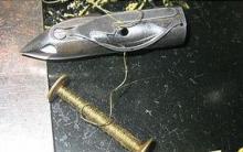
There was one more question - from what to make contacts. The ideal is a copper strip. The problem of the ideal is where to get it. Also, copper is non-magnetic and it would be necessary to put magnets on the field and on the blocks. Taking into account the fact that more powerful magnets would be needed to place them under the contacts (and this means both money and time for shipment), the search for a suitable material continued. And the eye fell on the staples for the stapler. The houses had staples of various sizes, they were steel (that is, they conducted current and were magnetized) and there were a lot of them.
As a result, the list of necessary components was determined - staples for stapler No. 35 (26/6 1 pack), neodymium magnets C-5x2-N35 and C-5x3-N35 with nickel coating (conductive), cardboard (microcorrugated cardboard left over from packages from - under photos and boxes), wire, solder, LED, resistor, microbulb, diode and button. To glue the parts, it was decided to use PVA glue, and an ordinary hole punch came up to punch holes for the magnets.
The materials were determined, the dimensions too (cell 40x40 mm, block 38x38 mm) and the direct process began.
The field is a sheet of cardboard, marked into squares 40x40 mm, the side faces of which are “stapled” in the center with a block of staples.

I took the staples the same as for blocks-cubes, but immediately made the first mistake. I did not see that the staples were covered with a non-conductive material on top and therefore had to be protected later. I also tried to tin them (which turned out to be not very high quality) and the size of the brackets should be taken more so as not to depend on the errors in the manufacture of blocks. If you decide to repeat this design, take staples about 20 mm wide and make a block 1 cm wide.
The staples were inserted into the slots in the cardboard and folded over reverse side. In the photo, the side wires are needed to "imitate" the common bus of the board game "Chain" and in the final version of the designer they will be replaced by blocks.
So, as a result of this painstaking work, we get a field with contact pads, to which our contact magnets are well magnetized.
Now it was necessary to make the blocks themselves with conductors and radio components. The problem was also that in the board game there were elements with a cross-shaped intersection and crossing conductors, and it was impossible to ensure the contact of all 4 magnets (remember how many points the plane passes through). Therefore, it was decided to abandon such blocks and make the maximum of T-shaped elements. For crossing elements, I plan to use special wire bridges in the future.
The block itself consists of three squares of cardboard measuring 38x38 mm. On average, holes are made for magnets and slots for brackets. On top of it, a second square is glued to the PVA glue only with slots for staples. After that, a small magnet 5x2 mm is installed in the hole, closed from above with a block of brackets that are bent on the other side. Radio components or conductors are soldered to them. On the other hand, we put magnets 5x3 mm and glue a square with holes. Due to the fact that the magnets "stick" to the magnets under the brackets, they hold very tightly and do not remain on the field.

Thus, we produce blanks with two and three magnetic platforms. Then solder the conductors or radio components.

We glue cardboard strips on top (two or three layers depending on the height of the parts) and close everything with a cardboard “lid”, on which we draw a designation with a marker (straight conductor, angular, T-shaped or radio element).
As a result, we got such a field and a set of details. I did not make the battery in the form of a block (although there is an idea to use a 5 V tablet in the future), but I made an element with two wires to which 3 batteries are connected.

During testing, it turned out that the bulb did not light up if there was an LED or a resistor in the circuit, and the LED could not be used without resistance (the smell of burnt plastic clearly showed this). Therefore, to simulate the gameplay, it was decided to assemble a “signal” circuit from another LED and a resistor on a breadboard, and simplify the game a little, leaving only one LED that needs to be “lit” to win. This turned out to be not critical, and this option was even more interesting, as it allowed changing the starting conditions of the game. The Circuit game itself in the tabletop version will also be redesigned and moved to a larger board, with multiple lamps and LEDs and different starting positions.
Cards were also prepared for the game, by drawing which the player understands which element he can use. Below is the final photo of the radio constructor game, as well as the game process.


Electronic constructor- great entertainment for the child, which allows you to combine the game with the acquisition of knowledge about physical world. Being engaged in the creation of electronic circuits, the child will get acquainted with the world of electronics and will get great pleasure from the gameplay.
The electronic designer is most useful for children. At this time, they receive basic knowledge about electronics, and playing with the designer allows them to deepen. The student has the opportunity to independently create a sound simulator, a voice recorder, or all these radio-electronic devices are contained in the abstract that comes with the designer.
Not only schoolchildren, but also younger children can play with the electronic designer. The fact is that to create an electronic circuit, the parts do not need to be soldered - they are connected using buttons. This allows you to easily and quickly do what you want. electronic device. And if you don’t like the result, then the details can be disassembled. And start all over again.

When purchasing an electronic designer, remember that only children over 4 years old can play with it on their own. The construction set contains many small parts that the baby can accidentally swallow. Therefore, if your child has not yet reached the recommended age, then assemble the electronic circuits yourself, and the child will watch with interest all the ongoing manipulations.
In the production of the designer, only environmentally friendly materials are used - non-toxic plastic and metal connecting elements. This ensures that (subject to the rules of operation) the parts of the designer will not emit any harmful chemicals.
Assembly of electronic circuits can be carried out both on the table and on a special plastic platform, which is included in the kit. But, of course, the second option is much more practical and convenient - the finished electronic device can be easily transferred from place to place, due to the fact that all its elements are fixed on a rigid and solid "substrate".

Electronic designers create different manufacturers. In Russia, the electronic designer "Expert" is especially popular. There are many reasons for this. It is noteworthy that the electronic designer can be produced in different variations (the number of schemes varies). Naturally, the more of them, the higher the price, since the kit includes additional parts.
As already mentioned, complete with a high-quality designer comes detailed instructions, in which you can find images of electronic circuits. The number of them depends on the variation of the designer. At the very beginning of the abstract there are schemes, the assembly of which is not particularly difficult - even a preschooler can design them. On subsequent sheets, the complexity of the circuits increases. It is better to start the game with the simplest options.
In general, an electronic designer is a great way to keep your child entertained with an exciting game that will increase their intellectual abilities. In addition, the game with the designer develops fine motor skills of the hands - in the future, when the baby learns to write, this will undoubtedly be beneficial. And for schoolchildren, the designer will facilitate the acquisition of knowledge about electronics and translate this process into a game form.
And what does foreign industry offer us? The stand for studying the basics of electronics allows you to build more than 200 different circuits. According to the instruction manual, there are 288 of them, but some have extremely minor differences.
The stand is supplied with connecting wires, detailed instructions for setting up experiments on English language, as well as the translation of this manual into Russian. Judging by the quality of the translation, it was done by machine or by a translator who is not very well versed in electronics. The printing performance of the translation is not high to make out, something on some diagrams is very difficult. However, due to the very small scale, many of the diagrams in the original manual also need to be disassembled with a magnifying glass. The main advantage of translation is that it exists at all. For a person who does not know English, this translation will still be useful. The connecting wires are insulated, single-core, so it is better not to bend them unnecessarily. The wires are given in quantity: 10 cm - 11 pcs, 20 cm - 12 pcs, 30 cm - 10 pcs, 40 cm - 8 pcs. The conclusions of electronic blocks and individual radio elements are made in the form of springs that securely fix the connecting wires, in any case, if the number of wires connected to one spring does not exceed 3-4.

The stand has a pointer ammeter. The scale of the device is graduated not in amperes, but in “parrots”.

The speaker is quite capable of performing the functions assigned to it.

The electric motor, in addition to its main function, also serves as a bell, for this a special hammer is put on the shaft, which, when the shaft rotates, hits the bell cup. The call is loud, good for demonstrations.

The stand is powered by four AA type galvanic cells, which are grouped in pairs in two blocks. A radio element is visible under the block, connected in series with galvanic cells, apparently this is a self-resetting fuse. In general, in real operation, I think it is not advisable to use batteries, since they are more sensitive to short circuits.

The main working field, where most of the stand elements are located. You can click to enlarge the photo.

There are radio elements on the stand for building a radio receiver. However, most of the radio receiver circuitry is a "black box". Although I don’t think that this is a very big drawback, because a novice radio amateur can only assemble a detector receiver. And it is not necessary to expect high-quality work from him, which can cause disappointment. At the stand, you can experiment with the oscillatory circuit of the receiver, the length of the whip antenna, so that some information about radio receivers will still be obtained. The diode, thyristor, npn- and pnp-transistors are located separately. Unfortunately, neither the documentation nor the stand itself indicates a specific type of semiconductor elements, which makes it difficult to repair, or to reproduce circuits separate from the stand.

Below the radio receiver there is a variable resistor, a container store, a microphone, a photoresistor, a switch, a touch panel.

On the right side of the stand there is a seven-segment indicator, a sound piezo emitter, and a panel of LEDs. There are specialized "black boxes" for playing different sounds.

In the lower right part of the stand there is a resistance box, an operational amplifier, a switch and a normally open reed switch. The stand comes with a number of accessories. Color wheel to show color mixing. It is put on the motor shaft, when rotated, the circle turns gray. In general, adding all the colors of the rainbow should result in white, but due to the inevitable imperfection in color, it turns out to be gray. The “fly” propeller should take off from the motor shaft, I did not succeed in doing this. The hammer is put on the motor shaft and turns it into an electric bell. The black tube at one end has a magnet to close the reed switch, the other end can be put on a photoresistor to darken it. Plastic clips are designed to disconnect the wires from the springs.

The stand is quite durable and after several years of fairly intensive (albeit careful) operation it is fully operational, the main design flaw is the underside of the stand, which is made of corrugated packaging cardboard. But in general, the stand can serve as an interesting gift for an inquisitive teenager. Thank you for your attention. Review prepared specifically for the site - Denev.
Discuss the article CHILDREN'S ELECTRONIC CONSTRUCTION AMAZING
The idea of creating an electronic construction set has been on my mind for a long time. As a child, I had an EKON-1 constructor and I wanted to create something similar, but at a modern level. The Connoisseur rules the ball on the market, there are also examples of modular constructors abroad, but the price and exchange rate are not pleasing to the eye.
On the other hand, there were interesting developments in the USSR (one of them still lives in Germany and is being produced):
I also wanted something “warm” in materials, such as wood. In 2014, within the framework of the PROSTOROBOT project, the idea of electronic cubes was born, which in 2015 even received a prize from AIDT for the idea at one of the qualifying stages of the Startup Tour.

It was also around this time that I came up with the logic board game "Circuit", which allowed "electrical circuits" to be played. The game can be freely downloaded and printed from the link.
Time passed. The cubes had to be put aside, since the price of magnets of the required power made them quite expensive. The game "Chain" waited for its turn to be finalized.
In 2016, I decided to return to the project and "got" the cubes. The first idea was to use the same cubes, but make fasteners like spring contacts and glue a cardboard box with cells, on the walls of which the contacts would be located:
The design turned out to be cumbersome, and due to the low rigidity of the walls, the cubes did not provide the desired quality of contact.
Engineering thought moved on. A small digression on the choice of material. Can you reasonably say why I did not use 3D printing or laser cutting? The answer is simple - I don’t have a 3D printer (more precisely, there is nowhere to put it in the apartment), and the nearest sane cutting in terms of price and quality is 500 kilometers from my city. Even finding thin plywood turned out to be an unrealistic quest, not to mention a special model one. Plus, I have long wanted to try the material familiar to fans of board games - cardboard.
The second option was to apply the method that I had already used earlier when designing Scratchduino - that is, 2.5 modeling of the constructor blocks themselves and magnets for fastening. This method did not require powerful expensive magnets, and at home I had a supply of cylindrical 5 mm magnets of different heights (2 and 3 mm).
It was also decided to first make a “physical” analogue of the board game “Chain”, since it required a field only 4x4, and then after collecting all the “bumps”, make the assembly field larger (at least 4x6, but better 6x8).
There was one more question - from what to make contacts. The ideal is a copper strip. The problem of the ideal is where to get it. Also, copper is non-magnetic and it would be necessary to put magnets on the field and on the blocks. Taking into account the fact that more powerful magnets would be needed to place them under the contacts (and this means both money and time for shipment), the search for a suitable material continued. And the eye fell on the staples for the stapler. The houses had staples of various sizes, they were steel (that is, they conducted current and were magnetized) and there were a lot of them.
As a result, the list of necessary components was determined - staples for stapler No. 35 (26/6 1 pack), neodymium magnets C-5x2-N35 and C-5x3-N35 with nickel coating (conductive), cardboard (microcorrugated cardboard left over from packages from - under photos and boxes), wire, solder, LED, resistor, microbulb, diode and button. To glue the parts, it was decided to use PVA glue, and an ordinary hole punch came up to punch holes for the magnets.
The materials were determined, the dimensions too (cell 40x40 mm, block 38x38 mm) and the direct process began.
The field is a sheet of cardboard, marked into squares 40x40 mm, the side faces of which are “stapled” in the center with a block of staples.
I took the staples the same as for blocks-cubes, but immediately made the first mistake. I did not see that the staples were covered with a non-conductive material on top and therefore had to be protected later. I also tried to tin them (which turned out to be not very high quality) and the size of the brackets should be taken more so as not to depend on the errors in the manufacture of blocks. If you decide to repeat this design, take staples about 20 mm wide and make a block 1 cm wide.
The staples were inserted into the slots in the cardboard and bent from the back. In the photo, the side wires are needed to "imitate" the common bus of the board game "Chain" and in the final version of the designer they will be replaced by blocks.
So, as a result of this painstaking work, we get a field with contact pads, to which our contact magnets are well magnetized.
Now it was necessary to make the blocks themselves with conductors and radio components. The problem was also that in the board game there were elements with a cross-shaped intersection and crossing conductors, and it was impossible to ensure the contact of all 4 magnets (remember how many points the plane passes through). Therefore, it was decided to abandon such blocks and make the maximum of T-shaped elements. For crossing elements, I plan to use special wire bridges in the future.
The block itself consists of three squares of cardboard measuring 38x38 mm. On average, holes are made for magnets and slots for brackets. On top of it, a second square is glued to the PVA glue only with slots for staples. After that, a small magnet 5x2 mm is installed in the hole, closed from above with a block of brackets that are bent on the other side. Radio components or conductors are soldered to them. On the other hand, we put magnets 5x3 mm and glue a square with holes. Due to the fact that the magnets "stick" to the magnets under the brackets, they hold very tightly and do not remain on the field.
Thus, we produce blanks with two and three magnetic platforms. Then solder the conductors or radio components.
We glue cardboard strips on top (two or three layers depending on the height of the parts) and close everything with a cardboard “lid”, on which we draw a designation with a marker (straight conductor, angular, T-shaped or radio element).
As a result, we got such a field and a set of details. I did not make the battery in the form of a block (although there is an idea to use a 5 V tablet in the future), but I made an element with two wires to which 3 batteries are connected.
During testing, it turned out that the bulb did not light up if there was an LED or a resistor in the circuit, and the LED could not be used without resistance (the smell of burnt plastic clearly showed this). Therefore, to simulate the gameplay, it was decided to assemble a “signal” circuit from another LED and a resistor on a breadboard, and simplify the game a little, leaving only one LED that needs to be “lit” to win. This turned out to be not critical, and this option was even more interesting, as it allowed changing the starting conditions of the game. The Circuit game itself in the tabletop version will also be redesigned and moved to a larger board, with multiple lamps and LEDs and different starting positions.
Cards were also prepared for the game, by drawing which the player understands which element he can use. Below is the final photo of the radio constructor game, as well as the game process.


Flower party: a bouquet of positive emotions
Words of teachers in a congratulatory scene for parents
Who's Who by Relationship Her mother-in-law calls her mother-in-law mom
Your mother is my mother-in-law Riddle mother-in-law calls my mother-in-law
How to make a scene for a wedding “Three girls under the window Comic scene three girls