Mankind has been striving upward for centuries and millennia; legends, myths, traditions and fairy tales are composed of people's attempts to overcome the earth's gravity. The ancient gods could move in the air on their chariots, someone did not even need them. The most famous "sky pilots" include Icarus, as well as Santa Claus (aka Santa Claus).
More real examples for history are Leonardo da Vinci, the Montgolfier brothers and other engineers, as well as enthusiasts who are passionate about their ideas, such as, for example, the American Wright brothers. The modern era of aircraft construction began with the latter, it was they who brought out some of the fundamental principles that are still used today.
As in the case of automobiles, the efficiency of aircraft grew over time, and designers got more opportunities to create some new, often revolutionary means of air transportation. With sufficient funding and support from those in power (more often - the military), it was possible to realize the most unusual projects. Often these were devices unadapted to life, which could only fly on paper. Others did get off the ground, but their production turned out to be too expensive. There were also other restrictions, including those of a technical nature.
We decided to list some both forgotten and promising aircraft for personal use. These are not aircraft for carrying a large number of passengers or bulky cargo, but individual means movements, attracting with their unusualness and theoretically capable of simplifying the life of a person of the future.
(Total 30 photos + 10 videos)
Sponsor of the post: Splitmart.ru - air conditioners, climate technology
HZ-1 Aerocycle (YHO-2)

1. The HZ-1 Aerocycle (YHO-2) is a personal helicopter developed by de Lackner Helicopters in the mid-1950s. The customer of the device was the US military, who intended to provide their soldiers with a convenient means of transportation. The Aerocycle was a platform, from below to which two propellers rotating in different directions were attached (the length of each blade was more than 4.5 meters).

2. They were powered by a 43 horsepower 4-cylinder engine, maximum speed unit flight - up to 110 km / h.

3. The YHO-2 was tested by professional pilot Selmer Sandby, who became a volunteer in this matter. His longest flight lasted 43 minutes, others ended a few seconds after takeoff. There were also incidents: several times the blades of two propellers touched, which led to their deformation, as well as loss of control over the apparatus.

4. It was assumed that anyone could fly the YHO-2 after a 20-minute briefing, but Sandby doubted this. The danger was carried by huge blades that could frighten a person, even though the pilot's position was fixed by seat belts. The engineers were never able to solve the problem with the propellers, and as a result, the project was closed. Of the 12 ordered personal helicopters, only one remained intact - it is exhibited in one of the American museums. By the way, Selmer Sandby received the Flying Merit Cross for his service and participation in the YHO-2 tests.
jetpack
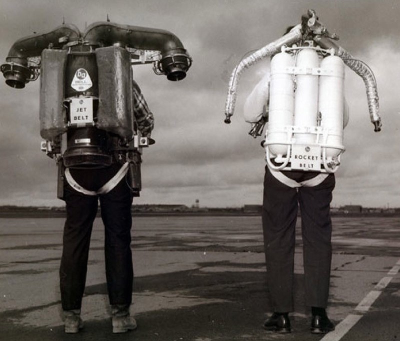
5. In the 1950s, another promising individual vehicle was being developed - the jetpack. This idea, which appeared in science fiction as far back as the 1920s, later found its embodiment in comics and films (for example, "The Rocketeer" in 1991), but before that, engineers and designers spent a lot of effort on realizing the idea of \u200b\u200bmaking a rocket man. Attempts have not stopped so far, but the level of technology development still does not allow to overcome some limitations. In particular, there is no talk of a long-term flight yet, controllability also leaves much to be desired. There are also questions regarding the safety of the pilot

6. The "pioneer" among rocket packs was distinguished by incredible "gluttony": a flight lasting up to 30 seconds required 19 liters of hydrogen peroxide (hydrogen peroxide). The pilot could effectively jump into the air or fly a hundred meters, but this was where all the advantages of the device ended. To maintain a single satchel, a whole team of specialists was required, its speed of movement was relatively low, and to increase the flight range, a tank was needed, which the pilot could not hold.

7. The military, who saw in a very expensive project the prospect of creating space infantry or flying special forces, were disappointed.
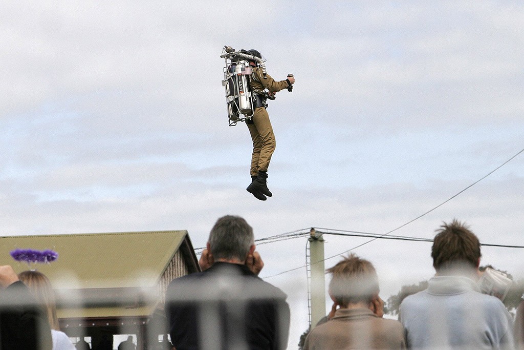
8. Subsequently, a modernized version of the device appeared - RB 2000 Rocket Belt. Its development was carried out by three Americans: insurance seller and entrepreneur Brad Barker, businessman Joe Wright and engineer Larry Stanley. Unfortunately, the group broke up: Stanley accused Barker of embezzlement and the latter fled with the RB 2000 sample. A court later followed, but Barker refused to pay $ 10 million. Stanley grabbed a former partner and put him in a box for eight days, for which, in 2002, after fleeing insurance agent received a life sentence (it was reduced to eight years). After all these ups and downs, the RB 2000 was never found.
Avro Canada VZ-9 Avrocar

9. In the late 1940s, the so-called Roswell Incident occurred, which probably influenced the minds of Canadian engineers. They took part in the development of the Avro Canada VZ-9 Avrocar VTOL aircraft. When looking at it, an analogy with flying saucers immediately comes to mind. The pilot project cost at least three years and $10 million. In total, two copies of the high-tech "doughnut" with a turbine in the middle were built.

10. It was assumed that Avrocar, using the Coanda effect (since 2012 it has been operated in Formula 1), will be able to develop high speed. Being maneuverable and having a decent flight range, it will eventually turn into a "flying jeep". The diameter of the "dish" with two cockpits for pilots was 5.5 meters, the height was less than a meter, and the weight was 2.5 tons. The maximum flight speed of Avrocar, according to the designers, was to reach 480 km / h, the flight altitude - more than 3 thousand meters.
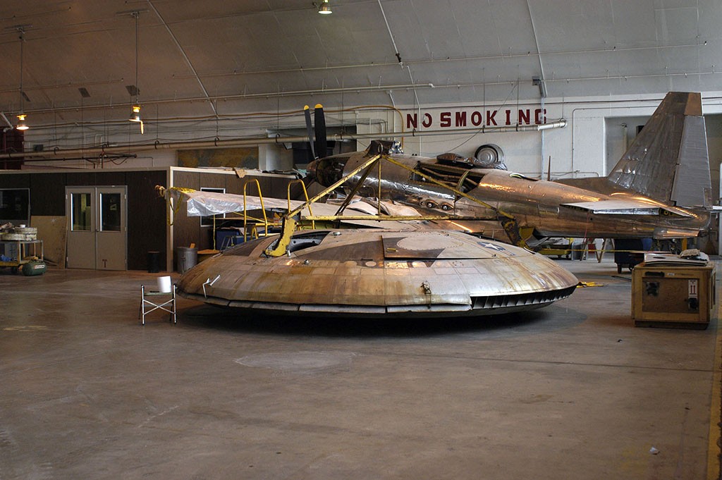
11. The second full-fledged prototype did not justify the hopes of its creators: it could only accelerate to an unimpressive 56 km / h. In addition, the device behaved unpredictably in the air, and there was no talk of an effective flight. The engineers also found out that it would not be possible to lift the Avrocar into the air to any significant height, and the existing sample risked getting stuck in tall grass or small shrubs.

AeroVelo Atlas bicycle helicopter

13. In 2013, two Canadian engineers received the Sikorsky Prize, established in 1980. Initially, its size was 10 thousand dollars. In 2009, payments increased to 250 thousand dollars. According to the rules of the competition, the muscle-powered aircraft had to take off into the air to a height of at least three meters, while having good stability and controllability.

14. The creators of AeroVelo Atlas were able to complete all the tasks, presenting in their own way a futuristic vehicle worthy of conquering the sky of a planet with low gravity. Despite its huge size (the width of the bicycle helicopter was 58 meters, and the weight was only 52 kg), the worthy successor to da Vinci's ideas took off and even in a sense surpassed the "competitor" in the face of Avrocar: its flight height was 3.3 meters, duration - over a minute.
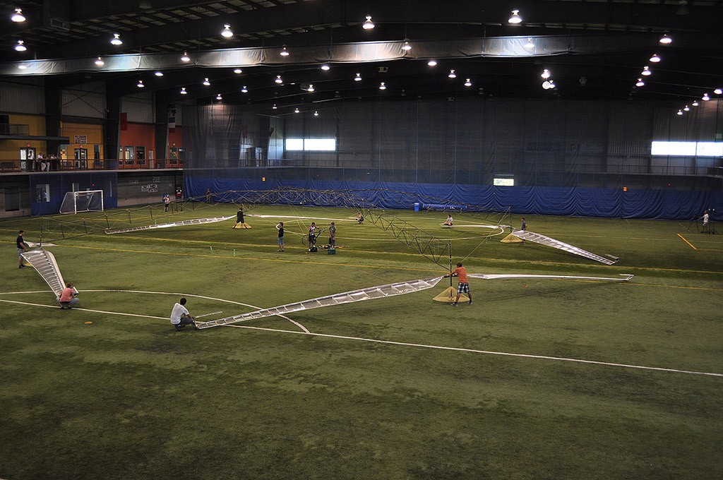
15. At peak, the Atlas pilot was able to generate the 1.5 horsepower required to reach the target altitude. At the end of the flight, the thrust was 0.8 horsepower - a trained athlete, a professional cyclist, pedaled.
A bicycle helicopter deserves attention as proof that, if desired, many obstacles can be bypassed and even something that does not inspire confidence at rest can be made to fly.
Hoverbike Chris Malloy

16. Someone is inspired by UFO stories and Chris Malloy is probably a fan star wars". So far, unfortunately, this is only an idea, partially embodied: the Australian continues to raise funds for the production of a fully working prototype of the aircraft.

17. To do this, he will need $ 1.1 million, but for now there are miniature versions of the hoverbike on sale: these are drones, through the sale of which Malloy intends to partially finance the construction of his offspring.

18. The engineer believes that his aircraft is better than the existing helicopters (it is with them that he compares the hoverbike). The unit does not require advanced knowledge in the field of piloting, as the main tasks will be performed by a computer. In addition, the device is lighter and cheaper.

19. It is planned that the device will be equipped with a tank of 30 liters of fuel (60 liters - with additional tanks), the flow rate will be 30 liters per hour, or 0.5 liters per minute. The width of the hoverbike reaches 1.3 meters, length - 3 meters, net weight - 105 kg, maximum takeoff weight - 270 kg.

20. The unit will be able to take off to a height of almost 3 km, and its speed will be more than 250 km/h. All this sounds promising, but so far it is unlikely.

21. A fully working water-powered rocket pack prototype was completed in 2008. According to its creators, the first draft of the future device appeared eight years before. A promo demonstrating the capabilities of the Jetlev was posted on YouTube in 2009, at the same time the developer company announced the cost of the first mass version of the device - 139.5 thousand dollars. Over time, the water-powered pack has noticeably decreased in price, which has decreased for the R200x model to 68.5 thousand dollars. This became possible due to the emerging competition.

22. In our list, this is the first aircraft that actually exists, works and has a certain popularity. It is “tied” to the water, but this does not detract from its merits: the maximum flight speed of the current model is 40 km / h, the height is about 40 meters. Given a sufficiently long river, a Jetlev pilot could cover almost 50 km (another question is whether there is a person who can withstand such a path).

23. The development does not claim to be a “serious” vehicle, but it will make you feel like James Bond, who has a new gadget from the British Secret Service Research Center.
M400 Skycar
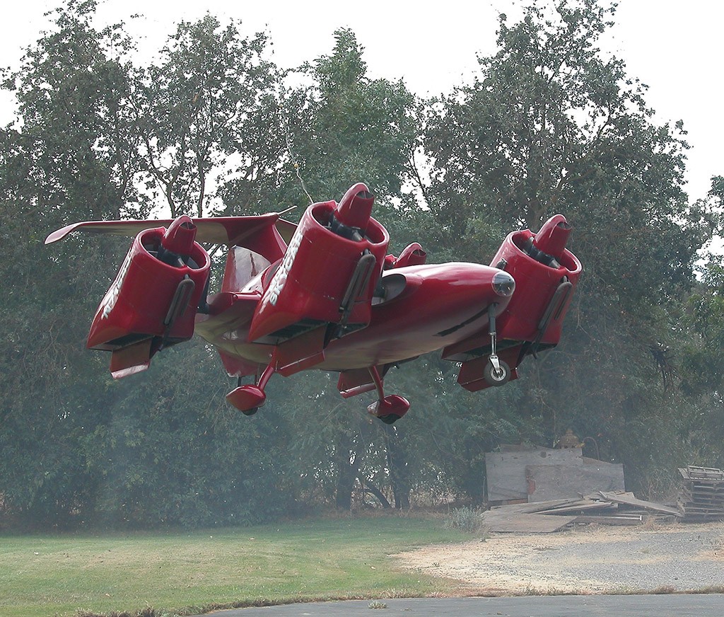
24. One of the most controversial projects, which in the end may not be implemented. The designer Paul Moller has been creating a flying car for more than a decade. In recent years, it has become increasingly difficult for him to draw attention to his vehicles that never took off. For all the time, the inventor has not been able to achieve significant and visible results, but at least since 1997 he has regularly attracted attention. financial services and regulatory bodies.
25. Initially, Moller was accused of issuing marketing materials in which he announced that his cars of the future would fill the airspace within a few years. Then doubts were raised by transactions with securities and a possible deception of investors, as a result of which there were fewer and fewer people willing to invest in a bottomless project. The Canadian made his last attempt at the end of 2013, but by January 2014 he had collected less than $30,000 out of the required $950,000.
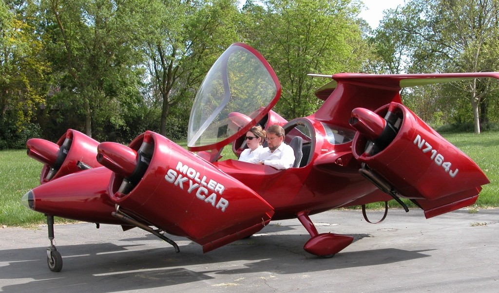
26. According to the designer, the M400X Skycar is currently under development. A car designed to carry one person (driver) is, on paper, capable of reaching speeds of up to 530 km/h and taking off to a height of 10,000 meters. In reality, the idea is likely to remain an idea, and Paul Moller's life's work, who turns 78 this year, will end in nothing.
Flying Motorcycle G2

27. In the future, it will definitely fly - this is evidenced by the tests of the first model carried out in 2005-2006. In the meantime, the device, which managed to win the title of "the world's fastest flying motorcycle", will suit Mad Max, Batman or 007.

28. Powered by a Suzuki GSX-R1000 engine, vehicle capable of reaching speeds of more than 200 km / h, which has been proven during races in the salt desert in the United States. The ability to conquer the sky, according to the developer, the flying motorcycle will receive in the coming months.

29. It was not in vain that the inventor chose a bike as the basis for the aircraft: according to American law, it will be much easier to register and use it on the roads.

30. Now Dejø Molnar is working on how to reduce the weight of the G2 and adapt the engine that drives the motorcycle to interact with the propeller. It was then that the engineer will publish a video demonstrating all the capabilities of the vehicle he is creating.
I turn on the high-voltage generator, and a light silver apparatus rises above the table to the quiet rustle of a corona discharge. It looks absolutely fantastic, and I'm starting to understand why the most amazing explanations for this phenomenon are found on the Internet. What kind of versions you will not find here - from the involvement of ethereal physics to attempts to combine electromagnetic and gravitational interactions. Popular Mechanics tried to clarify this issue.
Ion plane design
As an ion-plane, we decided to build the simplest design. Our apparatus is an asymmetric capacitor, the upper electrode of which is a thin copper wire, and the lower electrode is a foil plate stretched over a frame glued together from thin wooden (balsa) planks. The distance between the top wire and the foil is about 30 mm. It is very important that the foil goes around the strips and does not have sharp "ribs" (otherwise an electrical breakdown may occur).
We connected a high-voltage generator made from a modified power supply unit of a household air ionizer with a voltage of 30 kV to the resulting capacitor. Positive lead - to the top thin wire, negative - to the foil plate. Since the apparatus lacks a control and stabilization system, we tied it to the table with three nylon threads. After switching on the voltage, he broke away from the surface and hovered over the table, as far as the tether allowed.
We built the frame of the ion-plane from thin strips of balsa, gluing them together with cyanoacrylate glue. For the "sheathing" of the walls (the second electrode), thin aluminum foil was used, stretched over a frame (triangular in plan, with a side of about 200 mm) 30 mm wide. Please note that the foil does not have sharp edges and smoothly bends around the strips, otherwise the electric field strength near the surface will be very high, which can lead to breakdown. We made the upper electrode from thin copper wire with a cross section of 0.1 mm 2 (a winding wire with insulation removed was used) - a corona discharge occurs on it when high voltage is applied. The upper electrode (positive) is separated from the lower (negative) at a distance of about 3 cm. We attached the ionolet to the table with nylon threads so that it would not fly uncontrollably throughout the room.


Background
In the 1920s, American physicist Thomas Townsend Brown, while experimenting with Coolidge X-ray tubes, stumbled upon a curious effect. He discovered that a certain force acts on an asymmetric capacitor charged to a high voltage, which is even capable of lifting such a capacitor into the air. On November 15, 1928, Brown received British patent No. 300311 “Method for obtaining force or movement” for his apparatus. The effect of such a force was called the Biefeld-Brown effect because Paul Alfred Biefeld, professor of physics at Denison University in Granville, Ohio, assisted Brown in his experiments. The inventor himself believed that he had discovered a way to influence gravity with the help of electricity. Later, Brown received several more patents, but they no longer mentioned any effect on gravity.
In this form, this story is found almost everywhere on the Internet - in the articles of numerous unrecognized inventors of "anti-gravity devices" and "spaceships of the future." But our ion-plane really flies!
Power point
As a power plant (high-voltage generator), we used a power supply unit (PSU) from a household air ionizer with a voltage of about 30 kV. Since our ionizer had only one contact connected to the high-voltage electrode, we had to disassemble the case, remove the power supply itself and connect both leads. After that, we carefully placed the PSU in a box of a suitable size and filled it with paraffin for safety. Instead of a PSU, you can use the power supply of an old monitor (CRT).
Why does he fly
In fact, to explain the principle, it is not necessary to involve the mechanisms of "electrogravity" unknown to modern physics. As Yury Manoshkin, associate professor of the Department of General Physics at the Moscow Institute of Physics and Technology (MIPT), explained to Popular Mechanics, the whole thing is air ionization: “In this case, the field strength at one of the electrodes - the upper thin wire - is higher, a corona discharge occurs there, ionizing air. The ions are accelerated in the electric field of the capacitor towards the second electrode, creating a reactive thrust - the so-called ionic wind is formed. This, of course, is only a qualitative explanation of the effect, since, according to Yuri Manoshkin, “the theory of this process, which includes many aspects — gas discharge physics, plasma, and gas dynamics — is very complex and has not yet been sufficiently developed. But this issue is being studied, because in the future it has many quite serious applications. This is not about such flying toys, but, for example, about the possibilities of using ionization to influence the nature of the aerodynamic flow around aircraft.
We start a new game. We find ourselves in a train car. We go through training: look around, focus on the magazine, leaf through it, reduce it, look at the box, pick it up " small key» from its upper face, look at the suitcase, open its latches and then open the suitcase. We notice a small valve on the top cover, turn it and pick up " Eyepiece". Again we focus on the box, turn on the eyepiece and piece by piece collect the keyhole. Use the key on the keyhole and turn it. We pick up " Pyramid with symbols».
There is a small closed window in the door in front of us, we open the latch. We watch the departing Master, look around in the room in which we are. The marble table has 3 sides, turn on the eyepiece and read the inscriptions. It is necessary on each, rotating the drums by the lower edge, to set what is said in the inscriptions on this side. “The engine of flight, the source of knowledge” - a pen, “They are silent when we have nothing to show” - a watch, “The poor man does not have it, but the rich man is not boring” - nothing, an empty cell. We read the opened letter, pick up " Box with ornament". We poke on the box in the inventory to inspect it. Turning the ring on the front wall, open and pick up " lenses". We observe a silvery glow at the keyhole. Turn on the eyepiece and double-click to fly into the keyhole. We solve the puzzle with the lock: you need to install the pins so that they are on the same level. The correct level is highlighted in white. We pass into the central hall, inspect the table. Use the pyramid with the symbols on the white glowing triangle on the table. We pick up " Emblem", inspect the hall and move to family tree. We apply the emblem on the white oval and start a new mini-game: you need to choose the right coats of arms of the descendants.
We go into the opened arch and get into the office. We look at the generator, we need to start the current by moving the levers correctly. It's easy, you just need to observe the polarity: plus to minus, and minus to plus.

Turn on the lever on the window and watch the lights turn on at the lighthouse. We turn 4 switches on the device on a tripod and press the button. New mini-game: you need to set the correct frequency and amplitude of the signal on the oscilloscope by turning 2 knobs. The laser from the device opens a portal in the wall for us, we head there.
We get to the lighthouse. A hatch is visible on the floor to the left of the round table, move it aside and take it " Sphere hanging in a frame". There is a latch on the side of the table: you need to move it with one hand, and open the hook up with the other. Open the box all the way and take wooden tool". We insert it into the tower in the middle of the table, rotate it clockwise and observe the appearance of the island layout. Let's take a closer look at the resulting sphere in the frame: turn it over and twist it until it opens, take away from it " Magnet».

We head to the table on which there is a device with letters. Here you need to write the name of the island (PYRE). This is done as follows: the current letter is selected with the slider and 2 buttons are pressed so that the turned arrows point to the desired letter. We pick up " carved wooden frame". We examine the model on the table, insert it into a circle with two holes on a separate ledge and turn it.

We turn on the eyepiece and get inside the arch. We examine the columns: three of them have 2 round recesses: put 2 fingers on them and a figure lights up on the column. It must be repeated on the circle in the center.


On the tower that appears, we find a circle with arrows, turn on the eyepiece and make up the letters of the cardinal points.

We pick up " wooden model". We continue to inspect the tower, notice a small box with a handle, push it out and take the “Small clock face”. After that, we exit the archway. We examine the model of the island and insert the dial into the clock tower. We fly inside the tower and disassemble the owl model, at the end we get " boat model". We leave the tower, inspect the model of the island and find the pier. We put the wooden model from the inventory into the recess, put the model of the boat on the holder that appears, start the boat to the pier and fly into the building. We disassemble the mouse model and pick up " Key". We examine the model again and find a forge with a water wheel. We rotate it and fly into the opened window. We disassemble the snake model: pull the tail, combine 3 layers and pick up another one " Magnet". With these finds we go to the arch on the island. On the tower we find a rainbow circle with two round handles and insert magnets into them. We examine the tower and see on it 2 brass plates with symbols:


We pass to the circle with magnets, turn on the eyepiece and set the pimps on the tracks according to the picture on the map with the constellations. We pick up " wooden model". We go to the model of the island and put the resulting model as the second floor of the lighthouse tower. We insert the key into the keyhole on the 2nd floor of the lighthouse tower model and fly inside. We twist the handle, moving the parts of the mannequin and flying into the newly opened lighthouse models.
We examine the diving helmet standing on the pedestal: we turn the small switch in front and below to the correct position.

We pick up the rivet and remember the symbols on the plate:

We insert the rivet into the left porthole of the helmet and switch. We pick up " metal acorn". We examine it in more detail and, rotating the hat, open it into a key. Turn the switch in the recess where the acorn was taken from and pick up a new wooden model. We put it in the remaining place on the map. We turn the dome of the observatory and fly inside. We disassemble the grasshopper model and get " metal arrow". We insert the arrow into the dial at the diving helmet. We turn the handle, successively stopping at the three figures that we remembered earlier in the correct order.
We take away the copper faucet and put it on the valve below. We rotate the ovals on the helmet, bringing them to a vertical position, turn the unlocked wing nut and pick up " crystal vial» from the mouth of the skull. We examine the pedestal of the helmet and on the right side we put forward a flat box, taking from there " Antler» Again we go to the arch on the island. We insert the acorn-key into the picture of the tree, we insert the horn into the skull. Next, you need to turn the parts to achieve symmetry. We insert the crystal vial under the stone and take the " glowing gem". We insert it into the lighthouse model and take it " glowing lamp". The elevator descends, we go into it, we collect the central console together, turning, we rise to the lighthouse. Turning the upper and lower halves, open the window into which we insert a luminous lamp. We pick up a new Pyramid with symbols". Episode "The Lighthouse" completed!
We go to the central hall and put a new pyramid on the luminous triangle on the table. By turning the upper and lower parts we are trying to make a complete arch.

We go into the appeared passage and go to the library. We start the generator and go up the stairs.

We turn the switch by the window and observe the inclusion of the light on the street. We go down, turn 4 switches on the device on a tripod and press the button. Again a mini-game with an oscilloscope, only this time the frequency and amplitude must be selected by pressing two buttons. We go in the appeared passage and get into the clock tower.
We inspect the room and take " Wheel with handle» from the blue shield to the right of the clock mechanism. We examine the model on the table, throw the handle from above to the other side. We move 2 latches above the round disk behind the glass and open the door, take the " Small metal pole". We insert it into the metal frame on top and move it. Open the box, move the left panel on it. We go inside the appeared column. We open the round door on the right and take away " curved handle". On the left, rotate the central circle so as to align it with the pins, pick up the metal ring. We insert it into the front panel, rotate it until the square socket opens and insert the handle into it. We look at the puzzle that has opened from above: you need to move the panel up so that the same picture is in the slot as below, after that you need to move the slider to the right position.

We turn on the switch and see how 4 washers appear. They need to be driven into 4 pockets using manipulators from both edges. We go into the retractable block. We insert the handle into the square socket and, moving the blocks, drive the gear into the left circle. A familiar puzzle appears at the top: we make the picture at the top the same as the one at the bottom.

We take the "Gear". It must be inserted into the rotating wheel on the side of the clock mechanism. We go up the stairs that appear. We insert into the left wheel with a handle and rotate. We solve the puzzle with the picture: we put on the eyepiece, the luminous cloud must be brought to the bottom in the center, rotating the building and moving the cloud along the luminous lines. We pick up " Clock face”, go down and insert it into the model from the side. We solve the problem with the chess knight: they need to eat all the queens. Let me remind you that the horse walks with the letter "G". We fly inside the appeared block and bring all 3 levers to the center, rotating different objects. We open the central nest with levers and insert the handle there. Another picture matching puzzle.

We pick up " handle with socket' and go out into the room. Leaving, we take away the figure of the ballerina on the side of the chess puzzle. Insert the handle into the door gear and turn. We go down. We open the box, it turns out to be musical. We pick up " clockwork key»From the front panel, inspect the right one and move it. We turn on the eyepiece and collect the keyhole, into which we insert the winding key and turn it. Now the task is simple: you need to bring the ballerina to the center, opening the yellow tracks at the right time. When one is already in the center, put the second and repeat. We take the red gemstone” and insert it into the panel in the same room with other blue stones.

Next, you need to make pictures from the stones, which are shown below on the left and right. After each picture, you need to click the button above. Now, using the buttons on the right, you need to rotate the details of the sculpture so that you get a picture of a crow on the wall.

We pick up " Key with bird emblem”, go upstairs, insert it into the blue box on the wall and turn the switch. We go up the stairs again and watch the raven activate the bell. The sound breaks the crystal at the picture in the basement, we go there. Familiar mini-game with bringing a bunch of light down. We take the received Clock hands” and insert them into the clock face in the model in the first room. We insert the winding key into the socket and turn the clock hands. From the battle of the clock, the crystal breaks, and we can pick up a new pyramid. Episode "Clock Tower" completed!
People have been obsessed with the idea of taking to the air for centuries. In the myths of almost all peoples there are legends about flying animals and people with wings. The earliest known flying machines were bird-like wings. With them, people jumped from towers or tried to soar by falling off a cliff. And although such attempts ended, as a rule, tragically, people came up with more and more complex aircraft designs. Iconic aircraft will be discussed in our today's review.
1 Bamboo Helicopter

One of the world's oldest flying machines, the bamboo helicopter (also known as the bamboo dragonfly or Chinese spinner) is a toy that flies upwards when its main shaft is quickly spun. Invented in China around 400 B.C., the bamboo helicopter consisted of feather blades attached to the end of a bamboo stick.
2. Flying flashlight

A flying lantern is a small balloon made of paper and a wooden frame with a hole in the bottom, under which a small fire is kindled. It is believed that the Chinese experimented with flying lanterns as early as the 3rd century BC, but traditionally, their invention is attributed to the sage and commander Zhuge Liang (181-234 AD).
3. Balloon

The hot air balloon is the first successful technology of human flight on a supporting structure. The first manned flight was carried out by Pilatre de Rozier and the Marquis d "Arlande in 1783 in Paris in a balloon (on a leash) created by the Montgolfier brothers. Modern balloons can fly thousands of kilometers (the longest balloon flight is 7672 km from Japan to North Canada).
4. Solar balloon

Technically, this type of balloon flies by heating the air in it with solar radiation. As a rule, such balloons are made of black or dark material. While they are primarily used in the toy market, some solar balloons are large enough to lift a person into the air.
5 Ornithopter

The ornithopter, which was inspired by the flight of birds, bats and insects, is an aircraft that flies by flapping its wings. Most ornithopters are unmanned, but a few manned ornithopters have also been built. One of the earliest concepts for such a flying machine was developed by Leonardo da Vinci back in the 15th century. In 1894, Otto Lilienthal, a German aviation pioneer, made the first manned flight in an ornithopter.
6. Parachute

Made from lightweight and durable fabric (similar to nylon), a parachute is a device used to slow an object through the atmosphere. A description of the oldest parachute was found in an anonymous Italian manuscript dating back to 1470. In modern days, parachutes are used to lower a variety of cargo, including people, food, equipment, space capsules, and even bombs.
7. Kite

Originally built by stretching silk over a split bamboo frame, the kite was invented in China in the 5th century BC. Over a long period of time, many other cultures adopted this device, and some of them even continued to further improve this simple flying machine. For example, kites capable of carrying a person are believed to have existed in ancient China and Japan.
8. Airship

The airship became the first aircraft capable of controlled takeoff and landing. In the beginning, airships used hydrogen, but due to the high explosiveness of this gas, most airships built after the 1960s began to use helium. The airship may also be powered and the crew and/or payload located in one or more "gondolas" suspended below the gas cylinder.
9. Glider

Glider - an aircraft heavier than air, which is supported in flight by the dynamic reaction of air on its bearing surfaces, i.e. it is independent of the engine. Thus, most gliders do not have an engine, although some paragliders can be equipped with one to extend the flight if necessary.
10 Biplane

Biplane - an aircraft with two fixed wings, which are located one above the other. Biplanes have a number of advantages over conventional wing designs (monoplanes): they allow for more wing area and lift with a smaller wingspan. The Wright brothers' biplane in 1903 became the first aircraft to successfully take off.
11. Helicopter

A helicopter is a rotary-wing aircraft that can take off and land vertically, hover and fly in any direction. There have been many concepts similar to today's helicopters over the past centuries, but it wasn't until 1936 that the first working Focke-Wulf Fw 61 helicopter was built.
12. Aerocycle

In the 1950s, Lackner Helicopters came up with an unusual flying machine. The HZ-1 Aerocycle was intended to be operated by inexperienced pilots as the standard reconnaissance vehicle in the US Army. Although early testing indicated that the vehicle could provide sufficient mobility on the battlefield, more extensive evaluations indicated that it was too difficult to control for untrained infantrymen. As a result, after a couple of accidents, the project was frozen.
13. Kaitun
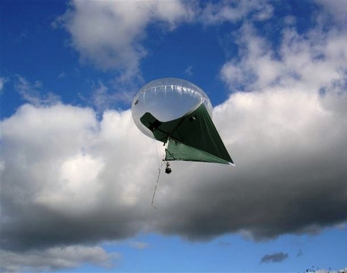
Kaitun is a hybrid of a kite and a hot air balloon. Its main advantage is that the kaitoon can remain in a fairly stable position above the anchor point of the cable, regardless of the strength of the wind, while conventional balloons and kites are less stable.
14. Hang glider

A hang glider is a non-motorized, heavier-than-air aircraft that lacks a tail. Modern hang gliders are made of aluminum alloy or composite materials, and the wing is made of synthetic canvas. These vehicles have a high lift ratio, which allows pilots to fly for several hours at an altitude of thousands of meters above sea level in the rising currents of warm air and perform aerobatics.
15. Hybrid airship

A hybrid airship is an aircraft that combines the characteristics of a lighter-than-air vehicle (i.e. airship technology) with a heavier-than-air vehicle technology (either a fixed wing or a rotary propeller). On the mass production no such designs were delivered, but several manned and unmanned prototypes were produced, including the Lockheed Martin P-791, an experimental hybrid airship developed by Lockheed Martin.
16. Airliner

Also known as a jet airliner, a jet airliner is a type of aircraft designed to carry passengers and cargo through the air, powered by jet engines. These engines allow the aircraft to reach high speeds and generate sufficient thrust to propel a large aircraft. Currently, the Airbus A380 is the world's largest jet airliner with a capacity of up to 853 people.
17. Rocket plane

A rocket plane is an aircraft that uses a rocket engine. Rocket planes can achieve much higher speeds than similarly sized jet aircraft. As a rule, their engine runs for no more than a few minutes, after which the plane glides. The rocket plane is suitable for flying at very high altitudes, and it is also capable of developing much higher acceleration and has a shorter takeoff run.
18. Float plane

It is a type of fixed wing aircraft capable of taking off and landing on water. The buoyancy of the seaplane is provided by pontoons or floats, which are installed instead of the landing gear under the fuselage. Float planes were widely used until the Second World War, but then they were replaced by helicopters and aircraft used from aircraft carriers.
19. Flying boat

Another type of seaplane, the flying boat, is a fixed-wing aircraft with a hull shaped to allow it to land on water. It differs from a floatplane in that it uses a specially designed fuselage that can float. Flying boats were very common in the first half of the 20th century. Like floatplanes, they subsequently fell into disuse after World War II.

Also known by other names (for example, cargo aircraft, freighter, transport aircraft, or cargo aircraft), a cargo aircraft is a fixed-wing aircraft designed or converted to carry goods rather than passengers. At the moment, the An-225 built in 1988 is the largest and most lifting in the world.
21. Bomber

Bomber - a combat aircraft designed to attack land and sea targets by dropping bombs, launching torpedoes or launching air-to-ground cruise missiles. There are two types of bombers. Strategic bombers primarily intended for long-range bombing missions - i.e. to attack strategic targets such as supply bases, bridges, factories, shipyards, etc. Tactical bombers are aimed at countering enemy military activities and supporting offensive operations.
22. Spaceplane

A spaceplane is an aerospace vehicle that is used in the Earth's atmosphere. They can use both missiles alone and auxiliary conventional jet engines. Today there are five such vehicles that have been successfully used: X-15, Space Shuttle, Buran, SpaceShipOne and Boeing X-37.
23. Spaceship

A spacecraft is a vehicle designed to fly in outer space. Spacecraft are used for a variety of purposes, including communications, earth observation, meteorology, navigation, space colonization, planetary exploration, and transportation of people and goods.

The space capsule is a special type spacecraft, which has been used in most manned space programs. A manned space capsule must have everything you need to Everyday life including air, water and food. The space capsule also protects astronauts from the cold and cosmic radiation.
25. Drone

Officially known as an unmanned aerial vehicle (UAV), the drone is often used for missions that are too "dangerous" or simply impossible for humans. Initially, they were used mainly for military purposes, but today they can be found literally everywhere.
To aircraft engines include all types of heat engines used as propulsion devices for aviation-type aircraft, i.e. devices that use aerodynamic quality to move, maneuver, etc. within the atmosphere (airplanes, helicopters, cruise missiles of classes "B-B", "V-3", "3-V", "3-3", aerospace systems, etc.). This implies a wide variety of used engines - from piston to rocket.
Aircraft engines (Fig. 1) are divided into three broad classes:
- piston (PD);
- air-jet (WFD including GTD);
- missile (RD or RKD).
The last two classes are subject to a more detailed classification, in particular the class WFD.
By principle of air compression WRDs are divided into:
- compressor , i.e., including a compressor for mechanical compression of air;
- compressorless
:
- once-through WFD ( SPVRD) with air compression only from velocity pressure;
- pulsating WFD ( PUVRD) with additional air compression in special intermittent gas-dynamic devices.
Rocket engine class LRE also refers to the compressor type of heat engines, since in these engines the working fluid (fuel) is compressed in a liquid state in turbopump units.
Rocket engine solid fuel (RDTT) does not have a special device for compressing the working fluid. It is carried out at the beginning of fuel combustion in the semi-enclosed space of the combustion chamber, where the fuel charge is located.
By operating principle there is a division: PD and PUVRD work in a cycle periodical actions, while WFD, GTD and RKD cycle is carried out continuous actions. This gives them advantages in terms of relative power, thrust, weight, etc., which determined, in particular, the expediency of their use in aviation.
By principle of jet thrust WRDs are divided into:
- direct reaction engines;
- indirect reaction engines.
Engines of the first type create tractive force (thrust P) directly - that's all rocket engines (RKD), turbojet without afterburner and with afterburner chambers ( TRD and TRDF), turbojet bypass (turbofan and TRDDF), once-through supersonic and hypersonic ( SPVRD and scramjet), pulsating (PUVRD) and numerous combined engines.
Indirect reaction gas turbine engines (GTD) transfer the power generated by them to a special propeller (propeller, propfan, helicopter main rotor, etc.), which creates tractive effort using the same air-jet principle ( turboprop , turbopropfan , turboshaft engines - TVD, TVVD, TVGTD). In this sense, the class WFD combines all engines that create thrust according to the air-jet principle.
Based on considered engine types simple circuits a number of combined engines , connecting the features and advantages of engines of various types, for example, classes:
- turbo-jet engines - TRDP (TRD or turbofan + SPVRD);
- rocket-ramjet - RPD (LRE or RDTT + SPVRD or scramjet);
- rocket-turbine - RTD (TRD + LRE);
and many other combinations of engines of more complex schemes.
Piston engines (PD)

Two-row radial 14-cylinder air-cooled piston engine. General form.
piston engine (English) piston engine ) -
Classification of piston engines. Aircraft piston engines can be classified according to various criteria:
- Depending on the type of fuel used- for light or heavy fuel engines.
- According to the method of mixing- on engines with external mixture formation (carburetor) and engines with internal mixture formation (direct fuel injection into cylinders).
- Depending on the method of ignition of the mixture- for positive ignition and compression ignition engines.
- Depending on the number of strokes- for two-stroke and four-stroke engines.
- Depending on the cooling method- for liquid and air-cooled engines.
- By number of cylinders- for four-cylinder, five-cylinder, twelve-cylinder engines, etc.
- Depending on the location of the cylinders- in-line (with cylinders arranged in a row) and star-shaped (with cylinders arranged in a circle).
In-line engines, in turn, are divided into single-row, two-row V-shaped, three-row W-shaped, four-row H-shaped or X-shaped engines. Axial engines are also divided into single-row, double-row and multi-row.
- By the nature of the change in power depending on the change in altitude- for high-altitude, i.e. engines that retain power as the aircraft rises to altitude, and low-altitude engines whose power decreases with increasing flight altitude.
- Propeller drive method- for motors with direct transmission to the propeller and gear motors.
Modern aircraft piston engines are four-stroke radial engines that run on gasoline. The cylinders of reciprocating engines are usually cooled by air. Previously, piston engines with water-cooled cylinders were also used in aviation.
Combustion of fuel in a piston engine is carried out in cylinders, while thermal energy is converted into mechanical, since under the pressure of the resulting gases, the piston moves forward. The translational movement of the piston, in turn, is converted into rotational movement of the engine crankshaft through the connecting rod, which is the connecting link between the cylinder with the piston and the crankshaft.
Gas turbine engines (GTE)
Gas turbine engine - a heat engine designed to convert the energy of fuel combustion into the kinetic energy of a jet stream and (or) into mechanical work on the engine shaft, the main elements of which are a compressor, a combustion chamber and a gas turbine.
Single-shaft and multi-shaft engines
The simplest gas turbine engine has only one turbine, which drives the compressor and at the same time is a source of useful power. This imposes a restriction on the operating modes of the engine.
Sometimes the engine is multi-shaft. In this case, there are several turbines in series, each of which drives its own shaft. Turbine high pressure(the first after the combustion chamber) always drives the engine compressor, and the subsequent ones can drive both an external load (propellers of a helicopter or a ship, powerful electric generators, etc.) and additional compressors of the engine itself, located in front of the main one.
The advantage of a multi-shaft engine is that each turbine operates at optimum speed and load. With a load driven from the shaft of a single-shaft engine, the throttle response of the engine, that is, the ability to quickly spin up, would be very poor, since the turbine needs to supply power both to provide the engine with a large amount of air (power is limited by the amount of air) and to accelerate the load. With a two-shaft scheme, a light high-pressure rotor quickly enters the regime, providing the engine with air, and the turbine low pressure plenty of gas for acceleration. It is also possible to use a less powerful starter for acceleration when starting only the high pressure rotor.
Turbojet engine (TRD)
Turbojet engine (English) turbojet engine ) - a heat engine that uses a gas turbine, and jet thrust is formed when combustion products flow out of a jet nozzle. Part of the work of the turbine is spent on compressing and heating the air (in the compressor).

Scheme of a turbojet engine:
1. input device;
2. axial compressor;
3. combustion chamber;
4. turbine blades;
5. nozzle.
In a turbojet engine, the compression of the working fluid at the inlet to the combustion chamber and the high value of air flow through the engine are achieved due to the combined action of the oncoming air flow and the compressor located in the TRD tract immediately after the inlet device, in front of the combustion chamber. The compressor is driven by a turbine mounted on the same shaft with it, and running on the same working fluid, heated in the combustion chamber, from which a jet stream is formed. In the inlet device, the static air pressure increases due to the deceleration of the air flow. In the compressor, the total air pressure increases due to the mechanical work performed by the compressor.
Pressure ratio in the compressor is one of the most important parameters of the turbojet engine, since the effective efficiency of the engine depends on it. If in the first samples of turbojet engines this indicator was 3, then in modern ones it reaches 40. To increase the gas-dynamic stability of compressors, they are made in two stages. Each of the cascades operates at its own speed and is driven by its own turbine. In this case, the shaft of the 1st stage of the compressor (low pressure), rotated by the last (lowest speed) turbine, passes inside the hollow shaft of the compressor of the second stage (high pressure). Engine stages are also called low and high pressure rotors.
The combustion chamber of most turbojet engines has an annular shape and the turbine-compressor shaft passes inside the chamber ring. Upon entering the combustion chamber, the air is divided into 3 streams:
- primary air- enters through the front openings in the combustion chamber, slows down in front of the injectors and takes a direct part in the formation of the fuel-air mixture. Directly involved in the combustion of fuel. The fuel-air mixture in the fuel combustion zone in the WFD is close to stoichiometric in composition.
- secondary air- enters through the side openings in the middle part of the walls of the combustion chamber and serves to cool them by creating an air flow with a much lower temperature than in the combustion zone.
- tertiary air- enters through special air channels in the outlet part of the combustion chamber walls and serves to equalize the temperature field of the working fluid in front of the turbine.
The gas-air mixture expands and part of its energy is converted in the turbine through the rotor blades into the mechanical energy of the rotation of the main shaft. This energy is spent primarily on the operation of the compressor, and is also used to drive engine units (fuel booster pumps, oil pumps, etc.) and drive electric generators that provide energy to various on-board systems.
The main part of the energy of the expanding gas-air mixture is used to accelerate the gas flow in the nozzle, which flows out of it, creating jet thrust.
The higher the combustion temperature, the higher the efficiency of the engine. To prevent the destruction of engine parts, heat-resistant alloys equipped with cooling systems and thermal barrier coatings are used.
Turbojet engine with afterburner (TRDF)
Turbojet engine with afterburner - modification of the turbojet engine, used mainly on supersonic aircraft. It differs from the turbojet engine by the presence of an afterburner between the turbine and the jet nozzle. An additional amount of fuel is supplied to this chamber through special nozzles, which is burned. The combustion process is organized and stabilized with the help of a front-end device that provides mixing of the evaporated fuel and the main flow. The increase in temperature associated with the heat input in the afterburner increases the available energy of the combustion products and, consequently, the speed of the exhaust from the jet nozzle. Accordingly, jet thrust (afterburner) also increases up to 50%, but fuel consumption increases sharply. Afterburner engines are generally not used in commercial aviation due to their low fuel economy.
Double-circuit turbojet engine (TRDD)
Lyulka A. M. was the first to propose the concept of a turbofan engine in the domestic aircraft engine industry (Based on research conducted since 1937, A. M. Lyulka submitted an application for the invention of a bypass turbojet engine. The copyright certificate was awarded on April 22, 1941.)
It can be said that from the 1960s to this day, in the aircraft engine industry, the era of turbofan engines. Turbofan engines of various types are the most common class of turbofan engines used on aircraft, from high-speed fighter-interceptors with low-bypass turbofans to giant commercial and military transport aircraft with high-bypass turbofans.

Scheme of a turbojet bypass engine:
1. low pressure compressor;
2. inner contour;
3. the output stream of the internal circuit;
4. output stream of the outer circuit.
The basis bypass turbojet engines the principle of attaching an additional mass of air to the turbojet engine passing through the external circuit of the engine was established, which makes it possible to obtain engines with a higher flight efficiency compared to conventional turbojet engines.
After passing through the inlet, the air enters the low pressure compressor, called the fan. After the fan, the air is divided into 2 streams. Part of the air enters the outer circuit and, bypassing the combustion chamber, forms a jet stream in the nozzle. The other part of the air passes through an internal circuit, completely identical to the turbofan engine mentioned above, with the difference that the last stages of the turbine in the turbofan engine are the fan drive.
One of the most important parameters of a turbofan engine is the bypass ratio (m), that is, the ratio of air flow through the external circuit to the air flow through the internal circuit. (m \u003d G 2 / G 1, where G 1 and G 2 are the air flow through the internal and external circuits, respectively.)
When the bypass ratio is less than 4 (m<4) потоки контуров на выходе, как правило, смешиваются и выбрасываются через общее сопло, если m>4 - streams are ejected separately, since mixing is difficult due to a significant difference in pressures and velocities.
The turbofan engine is based on the principle of increasing the flight efficiency of the engine by reducing the difference between the speed of the outflow of the working fluid from the nozzle and the flight speed. The reduction in thrust, which will cause a decrease in this difference between speeds, is compensated by an increase in air flow through the engine. The consequence of an increase in air flow through the engine is an increase in the area of the front section of the engine inlet, which results in an increase in the diameter of the engine inlet, which leads to an increase in its drag and mass. In other words, the higher the bypass ratio, the larger the diameter of the engine, ceteris paribus.
All turbofan engines can be divided into 2 groups:
- with mixing flows behind the turbine;
- without mixing.
In a turbofan engine with a mixture of flows ( TRDDsm) air flows from the external and internal circuits enter a single mixing chamber. In the mixing chamber, these flows are mixed and leave the engine through a single nozzle with a single temperature. TRDSM are more efficient, however, the presence of a mixing chamber leads to an increase in the dimensions and weight of the engine
Turbofan engines, like turbofan engines, can be equipped with adjustable nozzles and afterburners. As a rule, these are turbofan engines with low bypass ratios for supersonic military aircraft.

Military turbofan EJ200 (m=0.4)
Bypass turbojet engine with afterburner (TRDDF)
Dual-circuit turbojet engine with afterburner - modification of the turbofan engine. Differs in the presence of an afterburner chamber. Has found wide application.
The combustion products leaving the turbine are mixed with air coming from the external circuit, and then heat is supplied to the general flow in the afterburner, which operates on the same principle as in TRDF. The products of combustion in this engine flow from one common jet nozzle. Such an engine is called dual-circuit engine with a common afterburner.

TRDDF with deflectable thrust vector (OVT).
Thrust vector control (VCT) / Thrust vector deviation (VVT)
Special rotary nozzles, on some turbofan engines (F), make it possible to deflect the flow of the working fluid flowing out of the nozzle relative to the engine axis. OBT leads to additional losses of engine thrust due to the implementation additional work on the turn of the flow and complicate the control of the aircraft. But these shortcomings are fully compensated by a significant increase in maneuverability and a reduction in the takeoff run of the aircraft and landing run, up to and including vertical takeoff and landing. OVT is used exclusively in military aviation.
High Bypass Turbofan / Turbofan Engine

Scheme of a turbofan engine:
1. fan;
2. protective fairing;
3. turbocharger;
4. the output stream of the internal circuit;
5. output stream of the outer circuit.
turbofan engine (English) turbofan engine ) is a turbofan engine with a high bypass ratio (m>2). Here, the low-pressure compressor is converted into a fan, which differs from the compressor in a smaller number of steps and a larger diameter, and the hot jet practically does not mix with the cold one.
This type of engine uses a single-stage, large-diameter fan that provides high airflow through the engine at all flight speeds, including low takeoff and landing speeds. Due to the large diameter of the fan, the nozzle of the outer contour of such turbofan engines becomes quite heavy and is often shortened, with straighteners (fixed blades that turn the air flow in the axial direction). Accordingly, most turbofan engines with a high bypass ratio - no mixing.
Device inner contour such engines are similar to the turbojet engine, the last stages of the turbine of which are the fan drive.
Outer loop Such a turbofan engine, as a rule, is a single-stage large-diameter fan, behind which there is a directing vane made of fixed blades, which accelerate the air flow behind the fan and turn it, leading to an axial direction, the outer contour ends with a nozzle.
Due to the fact that the fan of such engines, as a rule, has a large diameter, and the degree of air pressure increase in the fan is not high, the nozzle of the external circuit of such engines is quite short. The distance from the engine inlet to the outer contour nozzle exit can be significantly less than the distance from the engine inlet to the inner contour nozzle exit. For this reason, quite often the nozzle of the outer contour is mistaken for a fan fairing.
Turbofan engines with a high bypass ratio have a two- or three-shaft design.
Advantages and disadvantages.
The main advantage of such engines is their high efficiency.
Disadvantages - large weight and dimensions. Especially - the large diameter of the fan, which leads to significant air resistance in flight.
The scope of such engines is long- and medium-haul commercial airliners, military transport aviation.

Turbopropfan engine (TVVD)
Turbopropfan engine (English) turbo propfan engine ) -


How to disable ads on Android: remove pop-up ads
The Russian received a term and a million fine for "piracy Negative consequences of the law
Identification of key factors
The criteria for classifying organizations and individual entrepreneurs as small and medium-sized businesses have changed
See what "Royalty" is in other dictionaries Pitfalls of legislation